Next: Results Up: Experimentation Previous: Experimentation Contents
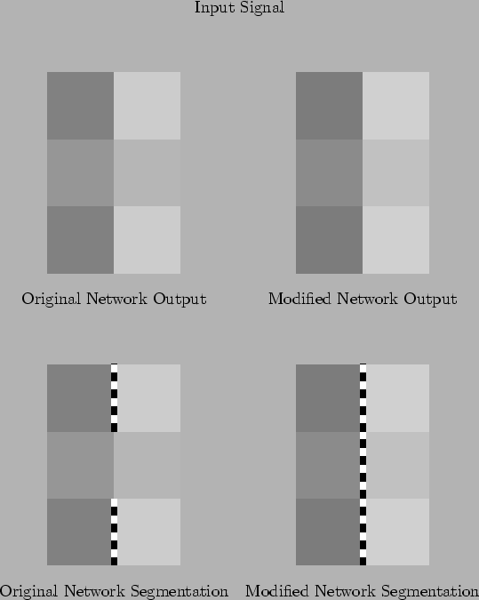
The entire circuit was implemented as SPICE subcircuits for testing. The C programs that create and decode the SPICE file were modified to introduce the new components. The circuit was then run through SPICE. The six pixel image shown earlier was tried again. For comparison, the output of both the simple resistive fuse network and the modified network are shown in Figure 7.1. As expected, the new network has done a better job of detecting the long edge down the centre than the simple resistive fuse network. This has reinforced the major feature of the image, with the dark region more consistently dark and the light region more consistently light.
Attempts to simulate larger networks with SPICE once again met with convergence problems. The simulation program was modified by adding a new class for the new network. This was simplified because the existing resistive grid class could be used for smoothing the differential signals.