Next: Diagonal Edges Up: Results Previous: Results Contents
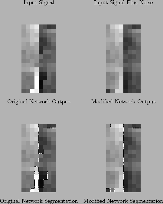
The first image that was simulated was a simple vertical line. The results
are shown in Figure 7.2. The noisy image contains an edge of
height 1V and uniformly distributed noise of ![]() 0.8V. Clearly, the
modified resistive
grid has done a better job of extracting the most important feature from the
image. Several features are notable. Firstly, the two gaps in the
segmentation of the resistive fuse grid have been filled in by the new
network. These gaps are not common in the output of the resistive fuse
grid, but when they occur they are a serious problem because of the way they
degrade the image. The effect is clear in the output of the resistive fuse
grid, where the signal has ``leaked'' through the gaps and blurred the edge. In
the modified grid, the edge is sharp all the way along, and the dark and
light regions are much more consistent over their entire area.
0.8V. Clearly, the
modified resistive
grid has done a better job of extracting the most important feature from the
image. Several features are notable. Firstly, the two gaps in the
segmentation of the resistive fuse grid have been filled in by the new
network. These gaps are not common in the output of the resistive fuse
grid, but when they occur they are a serious problem because of the way they
degrade the image. The effect is clear in the output of the resistive fuse
grid, where the signal has ``leaked'' through the gaps and blurred the edge. In
the modified grid, the edge is sharp all the way along, and the dark and
light regions are much more consistent over their entire area.
The light ``L'' shape in the output of the resistive fuse grid is due to the network segmenting according to the noise image and not the signal image. This is always going to be a problem when the noise amplitude is larger than the signal amplitude. However, because the shape is very thin, the two opposite sides tend to counteract each other in the modified network. In effect, the longer edge has ``won'' the contest, because it has received more reinforcement from its neighbours. As a result, the feature has not been segmented on one side, and it has been almost entirely smoothed out.
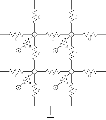
There are still edges in the output from the modified resistive fuse network, especially at the bottom left and top right corners. There is an important border effect in the modified network, which is simply due to the fact that there is less contextual information available at the edges and corners. Any errors tend to be in these areas. One problem though is that once one segment has erroneously tripped, it tends to reinforce other neighbouring edges to trip. This is why the error at the top right corner has run for two edge elements. For this reason, it may be worth adding extra discouragement to the border elements to prevent them tripping unless there is an overwhelming case for them to do so. This could be done by adding more resistors tied to ground, as shown in Figure 7.3.
Matthew Exon 2004-05-23