Next: Sub-threshold MOSFET operation Up: Eleven Transistor Resistive Fuse Previous: Eleven Transistor Resistive Fuse Contents
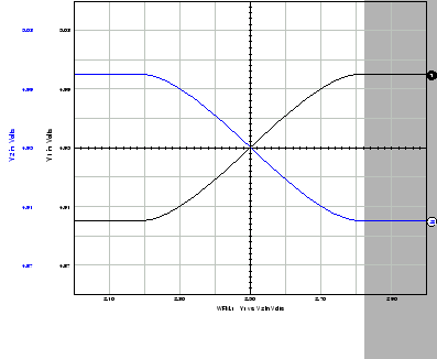
During the course of these investigations into better resistive fuse networks, a completely different design for a resistive fuse was tried. This design was based on simple differential pairs. In the subthreshold region, a MOSFET differential pair produces a tanh transfer characteristic as shown in Figure 4.10. The width of the transition region can be controlled by varying the geometry of the transistor. If the difference between the outputs of two differential pairs with different transition region widths is taken, then it will show a gentle resistive fuse characteristic.
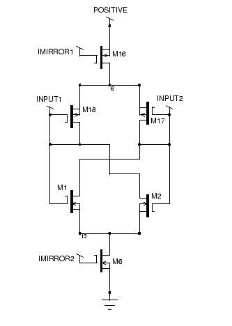
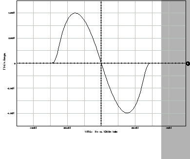
An implementation for this is shown in Figure 4.11. An N-channel differential pair and a P-channel differential pair are opposed. This means that the current is given by the difference between two of the characteristics in Figure 4.10. The width of the curves for each can be adjusted by controlling the geometry of the transistors in each differential pair. The cutoff point is given by the smaller of the two geometries, and the sharpness of the cutoff can be controlled by the larger of the two geometries. The circuit has all the common mode rejection properties of differential pairs. The characteristic of the circuit is shown in Figure 4.12
There are a few problems with this circuit, however. Firstly, the characteristic is too smooth, it should show a sharper cutoff. The cutoff can be made sharper by increasing the larger of the two geometries, but this reduces the maximum current of the device compared to the quiescent current. Furthermore, the cutoff point is fixed at the fabrication point. Therefore, the circuit was discarded for this application.
Matthew Exon 2004-05-23