Next: Six Transistor resistive fuse Up: Resistive Fuse Circuits Previous: Seven Transistor Resistive Fuse Contents
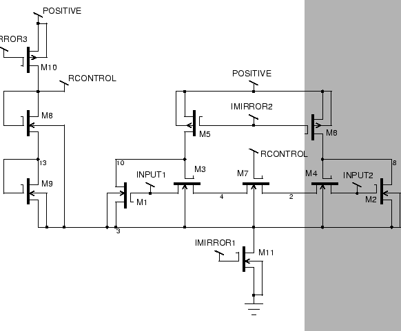
The third implementation is the eleven transistor fuse, which is an extension of the seven transistor version given above. The purpose of this extension is to allow the resistance of the fuse to be controlled electronically. The resistance is controlled by the current mirror line VBIAS. This means that a control circuit can be used to ensure that the resistance is always kept to a particular value.
The underlying concept of the eleven transistor fuse is to introduce a resistor between M3 and M4. This resistor should be large enough that the resistance of M3 and M4 can be largely ignored by comparison. Therefore, the variation in resistance due to common mode voltages can be ignored. Practically, of course, resistors are not used, but transistors. The circuit diagram is shown in Figure 4.7. The resistor is formed by M7. The resistance of this transistor is made to dominate by adjusting its geometry. For the purposes of this comparitive analysis M7 has a width/length ratio ten times that of M3 and M4. The specific value of its resistance is adjusted by changing the bias voltage, which is a global voltage line used in all the fuses on the chip. This achieves good common mode rejection and a very stable value of resistance. The cutoff voltage is still adjustable as before. Thus, the two important parameters of the device, the resistance and cutoff voltage, are independently and electronically controllable.
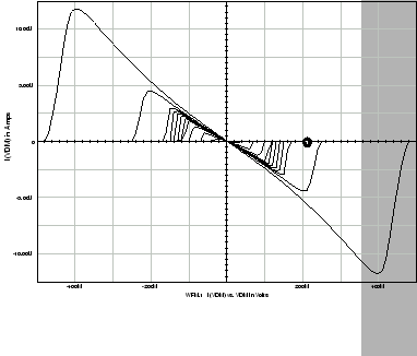
Simulation of the circuit at different common mode voltages is shown in Figure 4.8. The outermost curve is for a common mode voltage of 5V and the innermost one for 0V. This shows the great drawback of the eleven transistor resistive fuse, which is a strong dependency of the cutoff voltage on the common mode voltage. However, between common mode voltages 1.5V and 3.5V, the cutoff voltage is reasonably constant. Since the input voltages are unlikely to vary over the full supply voltage range, this limitation is not of great concern. Provided the input voltage is confined to between 1.5V and 3.5V, the circuit will demonstrate good performance. It should be noted that the resistance of the fuse is almost independent of common mode voltage.
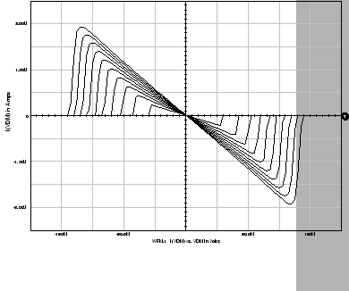
The effect of varying the bias current is shown in Figure 4.9.
The outermost curve is for a bias current of 1.9
![]() A, and the innermost
curve is for a bias current of 0.1
A, and the innermost
curve is for a bias current of 0.1
![]() A.
The purpose of the bias current is to control the resistance of the device.
As can be seen, excellent control over the resistance is provided by this
means. It will be noted that the cutoff voltage also varies - this is
because the cutoff voltage also depends on the bias current. Thus, in
order to set both the resistance and cutoff voltage, both
A.
The purpose of the bias current is to control the resistance of the device.
As can be seen, excellent control over the resistance is provided by this
means. It will be noted that the cutoff voltage also varies - this is
because the cutoff voltage also depends on the bias current. Thus, in
order to set both the resistance and cutoff voltage, both ![]() and
and ![]() need to be controlled.
need to be controlled.