Next: Implementation Up: Design of an Improved Previous: Methodology Contents
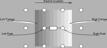
Initially, each edge element sees two voltages. If we arbitrarily decide that one voltage is on the ``left'' and the other is on the ``right'', then we can say that when the left-hand voltage is lower than the right-hand voltage, the edge element sees a positive spatial gradient. Otherwise, the edge element sees a negative spatial gradient. See Figure 6.2.
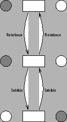
The edge element can then influence, and be influenced by, its neighbours. If it sees a gradient, it should encourage its neighbours above and below to preserve a gradient of the same sign, and remove a gradient of the opposite sign. If the gradient continues above and below, the edge elements will reinforce each other and the edge will be strengthened. Otherwise, the edge elements will counteract each other and the spurious edge will be eliminated, as shown in Figure 6.3.
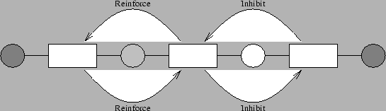
A similar process occurs in the horizontal direction. A noise point consists of a positive gradient right next to a negative gradient. Thus, if a positive gradient is detected, adjacent negative gradients should be discouraged, as shown in Figure 6.4. Note that this means that thin lines will be eliminated by this process. This is a problem in many areas of image enhancement, but for image segmentation this is a desirable property. For example, the whiskers on the Mandrill disguise the edge of the lips, see Figure 6.1. Eliminating them exposes the edge and the true segmentation area.
Thus the overall effect is to smooth the differential voltage signal of each resistive fuse over all its neighbours. This ensures that whatever the resistive fuses in a region are doing, they are all doing it consistently. To achieve this effect, a new resistive grid is introduced that connects the voltage difference signals. The output from this resistive grid is used to turn the resistive fuse on and off.
Matthew Exon 2004-05-23