Next: Triangle Up: Results Previous: Diagonal Edges Contents
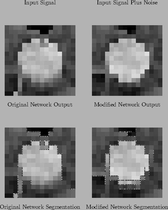
The next image simulated was of a circle object, see Figure 7.5. This object is actually quite small--although it takes up a large proportion of the region in these images, it is still only ten pixels across. This is about as small as any object that could be expected to be detected in an actual image. This circle, for example, is small enough that it could even be the dot on an ``i'' in an OCR system.
The resistive fuse network performs surprisingly poorly. While the top edge has been detected reasonably well, the bottom edge has really not been detected at all. As a result, the output intensity image is badly smudged. In the modified network, the bottom edge has been detected, and there is a much sharper edge. In fact, the network has produced three parallel segmentations. This rather surprising result is due to the fact that edge segments reinforce each other in the perpendicular direction as well as the parallel direction. Again, whenever edge segments erroneously trip, they are more likely to be around real edges. Further edge reduction processing would be more likely to succeed in this case than if the error edges were evenly distributed over the image, as they are in the simple resistive fuse network. Some form of edge thinning is still required to produce ideal results. The best thing about the modified network is that it has segmented the circle all the way around.
There is also a small cut in the top edge in the resistive fuse network output. This is clearly visible on the noisy input image. This is another example of noise signals being just as likely to be segmented as correct signals. The feature is too small to sustain itself in the modified network.
Matthew Exon 2004-05-23