Next: Motion Detection Up: Results Previous: Circle Contents
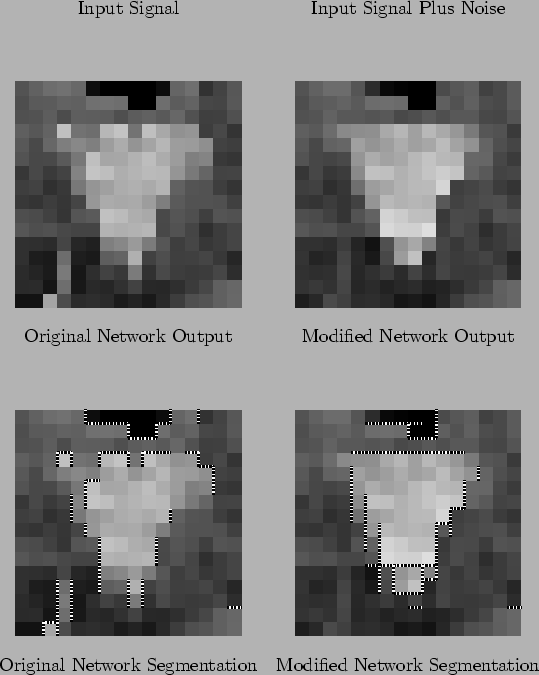
The triangle image (Figure 7.6) is important because you would expect acute angles to be difficult to detect by the modified network. Because the acute angles consist of opposing gradients, at the corners the two edges would tend to counteract each other, and you would expect the corners not to be detected at all.
This effect is visible at the two upper corners of the image. Neither of these two corners have been detected very well. However, the bottom corner has been detected well, even though it forms its own segment.
Overall, the resistive fuse network has performed extremely poorly in this image. In particular, when you look at the segmentation image, the edges that have segmented seem to bear little relation to the original image. As a result, the output intensity image is nothing more than shapeless blob. By comparison, the modified network has extracted a clearly triangular shape, and this shape is reflected in the output intensity image. The top edge is particularly clear. On the left edge, the segmentation is not complete; rather, a series of parallel edges have been detected. Clearly, the staircasing effect of the rectangular grid has meant that the horizontal edges are too far away to have a significant impact on each other.
Matthew Exon 2004-05-23