Next: Seven Transistor Resistive Fuse Up: Resistive Fuse Circuits Previous: Resistive Fuse Circuits Contents
The first resistive fuse is the four transistor fuse. This consists of two Chua resistors back to back, and provides a very simple implementation of the breakdown voltage behaviour of a resistive fuse. A Chua resistor consists of two depletion mode MOSFETS, connected as shown in Figure 4.1. The substrates of each transistor are connected to their drains. For simplicity of analysis, it is assumed that the threshold voltages of the transistors are equal and opposite, that is
![]() ,
,
and that the conductivity parameters are equal:
![]() .
.
Since the circuit is isolated from both the positive and ground voltage rails,
it is clear that it can only respond to differences between the
voltages on the two terminals of the device, and not to the common mode signal.
Thus, to analyse the circuit, it is only necessary to consider the
differential mode case where a signal ![]() is applied to the p-transistor
drain and
is applied to the p-transistor
drain and ![]() to the n-transistor drain. From symmetry, the voltage
at the node between the two transistors will be 0. Thus, it can be seen
that the operation of the transistors depends on the gate voltage always
being equal and opposite to the source voltage. As
to the n-transistor drain. From symmetry, the voltage
at the node between the two transistors will be 0. Thus, it can be seen
that the operation of the transistors depends on the gate voltage always
being equal and opposite to the source voltage. As ![]() is increased, the
current through the device will increase, until the gate voltage falls below
the threshold and the device shuts off.
is increased, the
current through the device will increase, until the gate voltage falls below
the threshold and the device shuts off.
If we start with a voltage signal ![]() , then no current will flow in the
circuit. If
, then no current will flow in the
circuit. If ![]() is increased slightly, both transistors will be in the
ohmic region, and
is increased slightly, both transistors will be in the
ohmic region, and
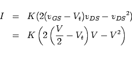
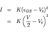
When ![]() ,
,
![]() , and the transistors pass into
saturation. Thus,
, and the transistors pass into
saturation. Thus,
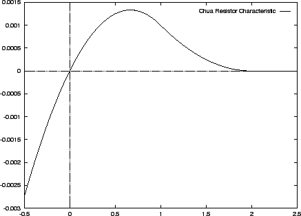
When ![]() , the transistors cut off, and the current becomes zero.
This characteristic is shown in Figure 4.2.
, the transistors cut off, and the current becomes zero.
This characteristic is shown in Figure 4.2.
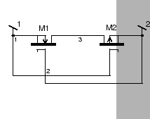
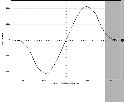
If two Chua resistors are placed back to back, the circuit will cut off for both positive and negative voltages larger than the threshold. The current through a reverse biased Chua resistor is very large. This means that the voltage across a four transistor resistive fuse will fall mainly across the forward biased Chua resistor. Thus, the characteristic for the total circuit will be the same as that of a single Chua resistor in the forward region, and a mirror image in the reverse region, as shown in Figure 4.3. There is no clear cutoff voltage, rather there is a gentle rolloff. The cutoff voltage will be the sum of the threshold voltages of the two transistors of a Chua resistor.
Because the substrate of each transistor is connected to its drain, the circuit is isolated from the supply rails, and thus the circuit displays excellent common mode independence. The major problem with the circuit is that its parameters, the threshold voltage and resistance, are determined at the fabrication stage, and the parameters of transistors are highly variable. Furthermore, depletion mode transistors are considerably more difficult to fabricate than enhancement mode transistors [4].
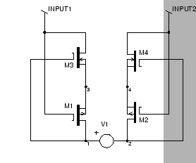
The schematic of my implementation of the four transistor resistive fuse is shown in Figure 4.4.