Next: Eleven Transistor Resistive Fuse Up: Resistive Fuse Circuits Previous: Four transistor resistive fuse Contents
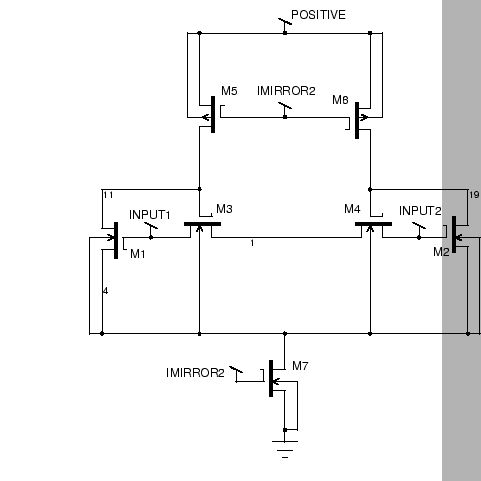
The second implementation of a resistive fuse is the seven transistor fuse, shown in Figure 4.5. Essentially, this consists of a differential amplifier, transistors M1 and M2, with an active load of two current sources, transistors M5 and M6. The output voltages of the differential amplifier are fed to the gates of two transistors M3 and M4 that are connected between the input terminals in parallel with the differential amplifier. Current between the two terminals is only possible through the transistors M3 and M4. The operation of the circuit is simple to understand. The differential amplifier creates a positive and negative difference signal. These signals control M3 and M4. When the difference signal becomes large enough in magnitude, the gate of either M3 or M4 will fall below threshold and the device will switch off.
The transistor M7 is biased to a suitable quiescent current, ![]() .
Since there could potentially be millions of these devices in the circuit,
this current is necessarily in the microamp range. The transistors M5 and
M6 are biased so that their saturation currents are each greater than
.
Since there could potentially be millions of these devices in the circuit,
this current is necessarily in the microamp range. The transistors M5 and
M6 are biased so that their saturation currents are each greater than ![]() :
:
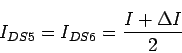
Because of this biasing arrangement, M5 and M6 cannot both be in saturation,
because there is no sink for the current ![]() . They therefore must be
in the triode region, with their drains close to the supply voltage. This
means that M3 and M4 have their gates close to
. They therefore must be
in the triode region, with their drains close to the supply voltage. This
means that M3 and M4 have their gates close to ![]() , and they are in the
triode region also. The total resistance of M3 and M4 is then given by:
, and they are in the
triode region also. The total resistance of M3 and M4 is then given by:
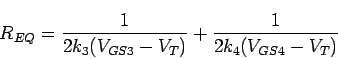
This resistance is clearly determined by the fabrication process.
The action of the differential amplifier is to steer more of the quiescent
current ![]() through one of M5 or M6. Once the current through M5 exceeds
the saturation current set by its biasing, the voltage of its drain will
decrease rapidly. The effect of this is to turn off M3, and there is no
longer a conducting path between the terminals of the fuse. This effect is
clearly symmetric. The cutoff point is the point where the drain current of
M1 or M2 equals the saturation current
through one of M5 or M6. Once the current through M5 exceeds
the saturation current set by its biasing, the voltage of its drain will
decrease rapidly. The effect of this is to turn off M3, and there is no
longer a conducting path between the terminals of the fuse. This effect is
clearly symmetric. The cutoff point is the point where the drain current of
M1 or M2 equals the saturation current
![]() . This gives the
cutoff voltage as:
. This gives the
cutoff voltage as:
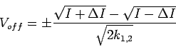
This is controllable by adjusting the quiescent currents ![]() and
and ![]() .
.
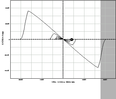
The seven transistor fuse was also implemented and tested. Its operation over several different values of common-mode signal is shown in Figure 4.6. The outermost curve is for a common-mode voltage of 4V and the innermost curve is for 1V. This clearly shows its strong dependence on the common mode signal, a property which makes it unsuitable for this application.
Matthew Exon 2004-05-23