Next: Transmission Up: Implementation Previous: Output Contents
The next thing to determine is how to control the behaviour of the resistive fuse. The resistive fuse consists of a differential pair with a load that consists of two current sources. These current sources nominally inject a current larger than the differential pair is drawing, and to resolve this inconsistency the voltages at nodes 10 and 8 have to be driven high enough to force the current sources into their ohmic region, in which case they no longer act as current sources. Through the operation of the differential pair, more current can be drawn through one side of the circuit, and this allows the voltage at node 10 (or node 8) to drop low, turning off the resistive fuse.
This behaviour can be modified by providing an additional current sink out of or into node 10. If current is injected into node 10, then transistor M1 has to draw more current before node 10 will drop. This has the effect of increasing the threshold at which the fuse cuts off. Similarly, by drawing current from node 10, the threshold can be reduced.
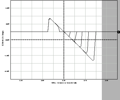
A simulation showing this effect is shown in Figure 6.5.
Current is
either injected into or drawn from node 10. The figure clearly shows
that the positive threshold is linearly controlled by this current, with the
largest threshold for an injected current of 0.7
![]() A. The
threshold can even be adjusted to lie in the negative gradient region, with
0.7
A. The
threshold can even be adjusted to lie in the negative gradient region, with
0.7
![]() A drawn from the node. This
would cause even a zero or slightly negative gradient to be classified as a
positive gradient, if the resistive fuse is biased far enough. The
negative threshold is not affected at all. This provides a powerful lever
with which to control the operation of the circuit.
A drawn from the node. This
would cause even a zero or slightly negative gradient to be classified as a
positive gradient, if the resistive fuse is biased far enough. The
negative threshold is not affected at all. This provides a powerful lever
with which to control the operation of the circuit.
Matthew Exon 2004-05-23