Next: Experimentation Up: Implementation Previous: Input Contents
The result of the above is that the output nodes of the resistive fuse are also the input nodes. This greatly simplifies the device that will be used for transmission.
The operation is as follows. Consider two adjacent edge components, see Figure 6.3. If edge A sees a positive gradient, thus causing node 10 to go low, then it needs to encourage edge B to detect a positive gradient by lowering the positive threshold, that is, by drawing current from node 10 in edge B. Note that if edge B has not detected a positive gradient, edge A may have detected a spurious edge, and so edge A has to be discouraged from detecting its positive gradient. This is done by injecting current into node 10 in edge A.
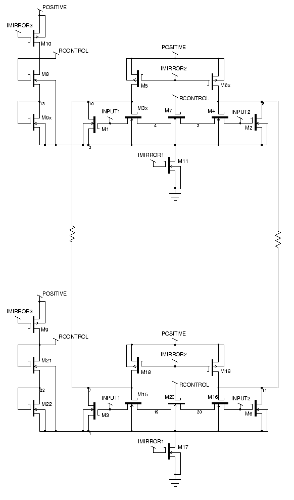
Thus when node 10 in edge A is low and is high in edge B, current needs to flow from B to A. This can most easily be achieved with a simple resistor, connected as shown in Figure 6.6. However, such a connection would cause a large current to flow, and the adjustments to current have to be extremely minor, of the order of less than a microamp. In order to produce such low currents, the transistor's geometry could be adjusted, but that would result in an extremely large transistor. Instead, the best solution is the five transistor circuit shown in Figure 6.7. This acts like a resistor over a small range, and then saturates to an easily controlled maximum current. Since the maximum current is controlled by the current mirrors, which mirror a global signal, yet another global control is provided to the operation of the circuit, which represents the amount of reinforcing and discouraging that occurs within the network.
All of this effectively forms another resistive grid. The source is the differential pair in each resistive fuse, the resistance is the resistance of the transistors forming the differential pair, and the conductance is the five transistor circuit. In fact, there are four resistive grids introduced by these modifications. There has to be a separate resistive grid for positive and negative gradients. Furthermore, the horizontal and vertical resistive fuses form two mutually orthogonal sets. that can't influence each other at all. All of this only adds the transistors that form the interconnections between resistive fuses--five transistors for each of four interconnections. This forms a total of 31 transistors for each resistive fuse, which even when multiplied by thousands of pixels, is still achievable on an integrated circuit.
Matthew Exon 2004-05-23