Next: Arbitrary Grids Up: Other Network Topologies Previous: Interlinking Vertical and Horizontal Contents
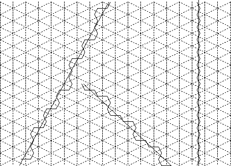
Another possibility is to use a hexagonal grid instead of a rectangular grid. A hexagonal grid is much less directional than a rectangular grid. In a rectangular grid, a perfectly vertical line will have all its edge segments perfectly aligned and these will reinforce each other strongly. Other edges will not have this benefit. In a hexagonal grid, a vertical line has none of its edges perfectly lined up, while horizontal lines have some of the edges perfectly lined up but others will be poorly lined up. Other edges have some combination of these two situations. Thus, all edge directions are treated more or less equally. This is shown in Figure 9.5. The receptors in the human retina form an approximately hexagonal grid, so this has a good basis in biological systems [13].
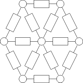
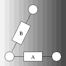
Obviously, the horizontal edges in Figure 9.6 should be connected just as in a rectangular grid. But the question of interconnections with the other edges is less obvious. We could simply adopt the same strategy as the original modified resistive grid, and have six separate resistive grids for the three different orientations of edges, but we would be better to use the strategy outlined in the previous section. Consider the two edges shown in Figure 9.7. The pixels can be considered to be sample points from a continuous intensity gradient shown on the diagram. Clearly this intensity gradient represents an edge. Both of these pixels should use the information they have at their disposal to reinforce each other.
The intensity gradient that A sees is twice what B sees, because of the orientation of the edges. This is the largest difference between the two edges that will ever be seen no matter what the angle of the intensity gradient. Therefore, the edges certainly have useful information to contribute to each other. The weighting that should be given to this information is again hard to judge, but it seems reasonable that since A can potentially see twice the gradient of B, then the resistance of this connection should be twice that of the connection between two parallel edge segments.